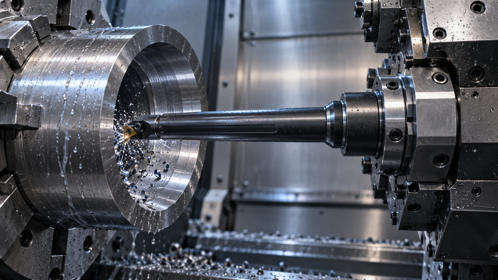
A damped boring bar holder must match both the machine and the bar. Start with the machine-side interface, then verify supported clamping length, bar diameter and head connection. A holder that accepts the nominal diameter can still leave too little supported length or create interference inside the bore. Damping cannot compensate for an unsuitable mechanical connection.
Map the complete connection chain
Write the assembly as machine station → holder → sleeve, if used → bar → cutting head. Identify the interface at every joint rather than ordering from a photograph. A cylindrical shank, modular connection and turret-mounted block are different interfaces even when their outside dimensions look similar.
For each joint, request the designation and mating drawing. Confirm whether the bar is fixed or adjustable in projection, where its clamping zone begins, and whether coolant passes through that joint. Do not assume a sleeve preserves coolant delivery or supports the full available clamping length.
Use a four-point fit checklist
| Check | Information to obtain | Reason |
|---|---|---|
| Machine interface | Turret or spindle interface and station limits | Establishes mounting compatibility |
| Clamping length | Permitted clamping zone and required engagement | Supports the bar without damaging functional areas |
| Bar diameter | Actual shank diameter, sleeve and bore fit | Nominal diameter alone does not define fit |
| Head connection | Connection designation and head orientation | Controls fit, access and cutting-edge position |
Ask for the tightening procedure as part of the holder specification. Use the applicable torque and sequence; extra tightening is not a substitute for the correct fit. Clean mating surfaces and inspect burrs or damage before assembly. Follow the manufacturer’s instructions on lubrication and screw replacement.
Check the assembly envelope at working reach
Use the component drawing to check the bar, cutting head, holder nose and coolant fittings throughout entry, cutting and withdrawal. The required reach is measured to the cutting edge, while the supported length refers to the clamped section. These dimensions answer different questions.
For example, a hypothetical holder may accept a bar diameter but put its nose too close to a bore shoulder. Reducing engagement to reach the shoulder could violate the clamping requirement. The solution is to select a suitable assembly, not to assume that a damped bar makes reduced support acceptable. Confirm tool-change and adjacent-station clearance as well.
Separate holder suitability from damping claims
BIG DAISHOWA’s vibration guidance treats assembly length and rigidity as setup concerns. Its Smart Damper material describes a specific manufacturer’s damped system. Neither establishes a universal clamping length or confirms the construction of an unrelated bar.
The related local damped-bar listing identifies a CNC internal-turning application, but does not confirm a complete holder interface or dimensional fit. Request a drawing of the proposed combination before treating it as a matched assembly. Retain the drawing and configuration designation with the quotation so a later substitution can be checked.
Send a complete holder enquiry
Include the machine interface, measured shank diameter, required cutting-edge reach, bore drawing, head connection, coolant route and available station envelope. Ask the supplier to identify any sleeve and fastening components in the offer. This produces a checkable assembly rather than a loose recommendation to buy a stronger holder. Record the selected sleeve and fasteners on the same assembly sheet.
Frequently asked questions
Is matching the bar diameter enough?
No. Confirm the interface, supported clamping length, sleeve fit, head connection and clearance as a complete assembly.
What clamping length should I use?
Use the minimum engagement and permitted clamping zone specified for the exact bar and holder. There is no universal value for all damped bars.
Can I clamp over any part of a damped bar?
Do not assume so. Obtain the manufacturer’s drawing and clamp only within its approved zone using the specified procedure.
Related selection resources
Damped boring bar configuration · Damped-bar specification checklist · How damping works
Technical references and scope
Manufacturer references explain general selection principles or their own systems; they do not certify another supplier’s compatibility or performance. Product ranges above come from the linked local listings. This guide does not replace instructions for the exact assembly. Sources reviewed October 27, 2026.
Technical information is prepared by the Wujinniu CNC tooling team based on product application data and machining requirements.