
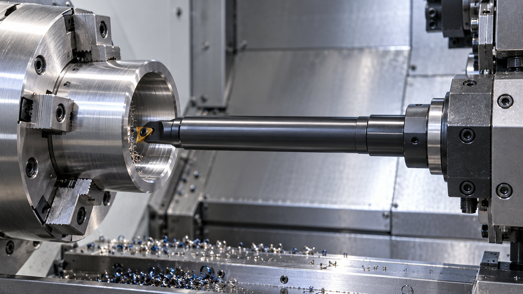
If chatter continues after installing a damped boring bar, first verify the new assembly and its support conditions. Do not assume the next step is a larger speed reduction or another bar. A wrong sleeve, dirty joint, unsuitable insert or unsupported workpiece can prevent the expected improvement.
Establish a reliable before-and-after record
Record the old and new assembly, projection to the cutting edge, holder, head, insert and workpiece setup. Note exactly where the mark appears: at entry, along the whole bore, at a shoulder, or only after the tool becomes hot. This is a diagnostic record, not proof that any single component is at fault.
Stop cutting before inspecting the assembly and follow machine isolation procedures. Check for a damaged edge, loose fastening, rubbing or trapped chips. Repeated trial cuts with a suspect connection can obscure the original symptom and damage the part or tooling.
Start with changes introduced during installation
The following check order is an editorial worksheet based on the cited general vibration guidance. It is not a manufacturer-prescribed repair procedure.
| Check | Evidence to collect | Next action |
|---|---|---|
| Clamping zone and engagement | Assembly drawing and actual projection | Restore the approved clamping arrangement |
| Sleeve and mating faces | Fit, cleanliness and visible damage | Correct the connection before cutting |
| Head seating and orientation | Connection designation and edge position | Assemble to the system instructions |
| Fasteners | Correct parts and tightening procedure | Use specified sequence and torque |
Do not clamp across an unapproved section or compensate for a fit problem with extra screw torque. If the bar requires system-specific adjustment, verify its setting with the supplier. The local listing does not confirm an adjustment method, so do not improvise one.
Inspect the cutting edge and bore clearance
Confirm that the head and insert are suitable for internal turning and the material. Check the actual cutting edge, not just the insert box. A chipped or heavily worn edge changes the cutting load; an unsuitable geometry can create forces the assembly struggles to support.
Check center height, orientation and clearance along the entire cutting path. Rubbing behind the cutting edge or interference at a shoulder can resemble a stability problem. Chip packing is another separate source of disturbance: inspect the chip path and coolant delivery instead of assuming the damper is defective.
Check the workpiece side of the system
A thin wall, long unsupported section or changing support condition can vibrate even with a damped tool. Compare the symptom with workpiece geometry. If the problem is concentrated near a weak section, review clamping distortion and workpiece support before replacing the bar.
Bore size and finish should be inspected using the drawing requirements and a suitable method. A change in sound is useful observation, but it does not prove acceptable geometry. Distinguish chatter marks from built-up edge, chip scratching and rubbing; each points toward a different correction.
Run one controlled change at a time
Once mechanical checks pass, review cutting data against the recommendations for the actual tool, insert and material. Keep a short log of each change and its measured result. Avoid changing speed, feed, depth, insert and projection together, because the result becomes difficult to interpret.
BIG DAISHOWA’s vibration guidance provides a basis for reviewing rigidity, assembly length and support. Apply it as general guidance, then use configuration-specific limits from the bar supplier. Escalate with photos of the marks, the assembly drawing, projection, material and trial log if the process remains unstable.
Frequently asked questions
Should I reduce speed immediately?
First rule out incorrect assembly, damage, interference and poor support. Then adjust cutting data within the guidance for the actual tool and material.
Can the workpiece still chatter with a damped bar?
Yes. A flexible or poorly supported workpiece remains part of the vibrating system.
What should I send the supplier?
Send the assembly designation, projection, holder and head details, material, insert, cutting conditions, photos of the marks and the changes already tested.
Related selection resources
Damped boring bar selection · Clamping and interface checks · Damping versus stiffness
Technical references and scope
Manufacturer references explain general selection principles or their own systems; they do not certify another supplier’s compatibility or performance. Product ranges above come from the linked local listings. This guide does not replace instructions for the exact assembly. Sources reviewed October 27, 2026.
Technical information is prepared by the Wujinniu CNC tooling team based on product application data and machining requirements.